This is a companion post to my prior post titled Ceiling Fan Capacitor Woes which details the search for a supplier of replacement capacitors to restore several broken ceiling fans to full working order. That post also linked to a number of reference sites, and if this topic is interesting, but confusing, it is suggested to refer back to its links. This posting details knowledge I’ve gained in the process of successfully replacing ceiling fan capacitors that had blown, but additionally, understanding of how to alter the fan blade’s revolutions per minute (RPM). To my knowledge and data searches, this speed-alteration information was not detailed elsewhere. Many sites offered hints, presented, to my mind, in a puzzle-like form of bits and pieces, and none of which showed the bigger picture which I felt I needed to both understand how the various capacitor values worked, and minimize the number purchased, unless I simply wanted precise factory-specified microfarad-valued replacements. Even the manufacturer of the fans didn’t seem to include either a detailed or basic schematic of their circuit, something that is historically quite common for appliances.
In some respects, my prior post created more questions as well as providing some answers, but first. . . .
Disclaimers
Legal: Nothing below is intended for your repair use, but for informational purposes only. Information I learned, then logicized from, is provided as is: it is potentially flawed, and possibly highly flawed. This work has not been reviewed by any competent third party. If you make any attempt to repair or alter your fan after reading this post, and something bad or catastrophic happens, or less severely you end up wasting much time, consider yourself warned. I advised you not to repair or alter your fan.
If you decide to ignore my advice and do-it-yourself, then electrically appropriate precautions need to be followed, this includes turning off the circuit breaker so the fan’s wiring has no supplied power along with verification of this at the fan, and basic recording of wire colors and connections before disassembly, so that reassembly is not interrupted by confusion regarding what wire went where. It is also presumed you know that even with the power turned off, capacitors store electricity and can discharge this electricity at unexpected moments, so discharging them before handling any of the wiring is recommended using appropriately insulated tools.
Skip all the rigamarole with quick start to altering fan speeds.
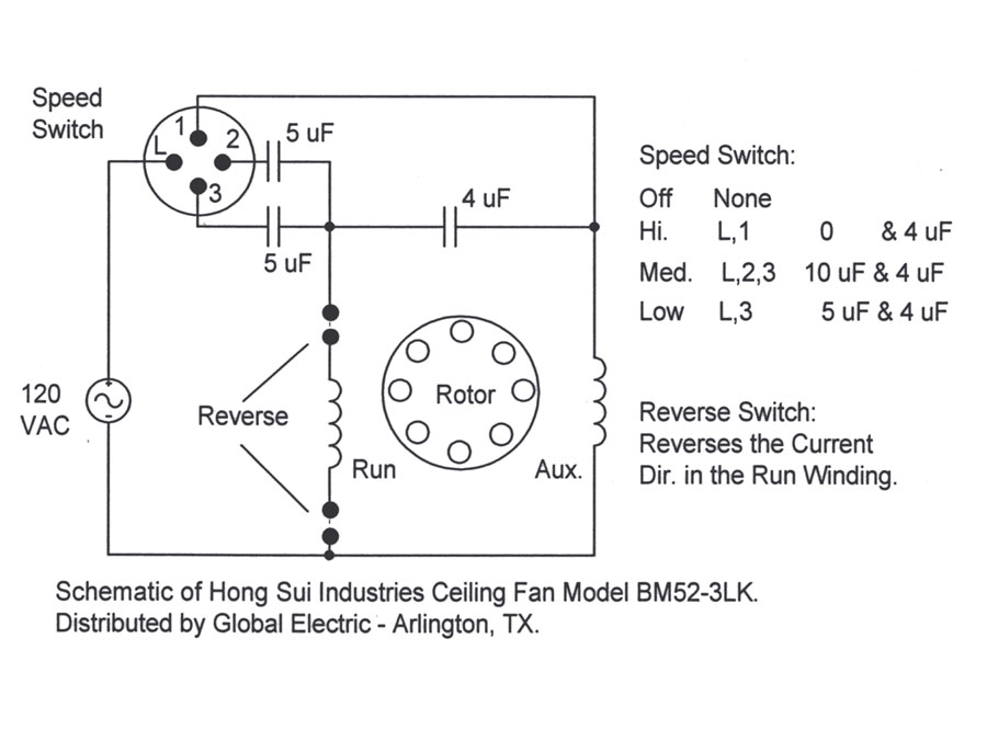
Important: this post, the problem, the functions, the graphs, the spreadsheet, the replaced speed switch problem, the discussion, the installation, the final summary, and any other section or concept I’ve not mentioned: all apply only to one particular schematic, not reproduced on this page, but a likely candidate was found, a simplified three-capacitor ceiling-fan schematic, which uses one particular speed switch. If the fan uses another kind of speed switch from those two discussed herein, then my system of sorts won’t work as presented, at least not without some changes, possibly minor; or if the fan has two capacitors for three speeds, or is wired to any other schematic, my system of sorts also won’t work as presented.
It’s also important to understand that the chain-pull speed switch is altogether different from the reverse switch. For a short discussion of the DPDT reverse switch relative to the simplified schematic, something I overlooked when originally writing this post, please see comment #15, there are some links to generic yet detailed reverse switch schematics.
Clearly, it is easiest and fastest to replace any blown capacitors with precisely equivalent values the factory used, if they are available; the same seems true of switches. This exact or precise replacement advice is, at the time of this writing, consistent with the vast majority of webpage ceiling fan FAQs easily found using search engines.
I must listen to the beat of a different drummer.
. . .  Introduction continued
After learning or realizing speeds could be altered, I decided that two fans in rather small rooms would be preferable running at somewhat slower than factory speeds, so making an informed guess as to which possible microfarad value capacitors to purchase took some study and spreadsheet creation time — quite a bit of time if one also includes writing about it. Not only did I want two of the fans slower overall, I particularly wanted to change medium speed’s relationship to high and low, from being rather close to high, to being closer to low, or at least be solidly in the middle judging from the breeze created. It’s possible to increase or decrease the range or distance, or fan-speed RPM variance, from high to low, and I decided I wanted less variance in those smaller rooms, high speed moved the air too fast and wasn’t used, and I wanted low to be slower.
Consequently, I needed to devise my own ideas regarding how these capacitors worked in the motor’s circuit for speed control purposes, and I needed to do this with all due haste, without becoming an electronic engineer, without spending years attempting to unravel the highly-complicated theories of hundreds of thousands of highly-precise past & present academics en masse, and without spending additional money beyond capacitor-module replacement. Fortunately, I was able to assemble other great web writers’ brief ideas, even if they were only presented in bits and pieces, into a system of sorts that allowed me to alter ceiling fan speeds by altering the capacitors values without needing to buy every available capacitor value and try them out by installation, followed by removal, and replacement with another, etcetera, until by sheer luck a combination of microfarad values were found that provided satisfactory fan speeds.
It’s rather ironic to remember that in my prior post I wrote I wanted a “quick and simple” solution.
This posting is intended for my own future reference. It has been through a number of revisions, as more information and further insights were added, at the time, to the only existing section which has now become the reorganized discussion section, the original post’s overall structure became more confusing, so a final (ha ha) restructuring seemed in order, and to some degree, is presented in the reverse order that it was originally written for inclusion. While the functions and graphs were one of these items added near the end during later revisions, included after I’d had several light-bulb moments due to the actual writing process, the spreadsheet was one of the first, and it uses the same functions or formulas. Much of the information presented is potentially confusing, some math is involved, and there are no guarantees that even the concept of my system of sorts has any basis in accepted or correct electronic theory, though it did work for my purposes.
Read at your own risk.
The nitty-gritty is found in the final summary at the end of the post, and should be accurate to the best of my knowledge; the replaced speed switch drawing of the chain-pull switches’ power-routing logistics should not be skipped, since there are multiple variations of switch logistics. Tracing the capacitors’ wires to the speed switch is also a good way to label capacitors one (C1), two (C2), and three (C3).
If you are formally trained and experienced in electronics, unlike myself, and you happen to read this post, any suggestions for improvement, or even a “You’re nuts!” followed by ‘the why’ rationale, would be appreciated. The spreadsheet calculations do seem to have one issue that I cannot resolve at this time, it’s explained below, and there may be others. Terminology I’ve used may not be what is typical when used by specialists.
The Problem

It’s always nice to know what one blown capacitor module looks like. The deformation on the side is quite visible, but there’s some on the left front as well. It’s understandable why, for ceiling fans, the capacitors are encased in injection-molded plastic and pourable epoxy. Unfortunately, the only way provided by the manufacturer to remove the module was to cut the wires. After the low-speed capacitor blew, this particular module continued to work on two remaining speeds before removal for well over a year of intermittent usage. It seems there are still two good capacitors in it.
Another module with a blown capacitor showed less-obvious case damage, but the purple wire was quite scorched, it’s color significantly darkened for about the first 1/2-3/4 of an inch measuring from the black epoxy. Apparently, before blowing, it seems capacitors get quite hot.
Replacement of the factory’s chosen microfarad values should be easy enough if those precise values are available, but how does one also alter the fan’s speed?
Functions
This section discloses the functions I conceived for ceiling fan speed alteration, after reading, and thinking about, web-based research fully disclosed in my prior post. I thought I could calculate the Capacitors’ Microfarad-Values Difference supplied to the two motor coils, what I have named Coils’ Δ (Δ = Delta or difference) in the tables below, and come up with an abstraction that relates, however imperfectly, to the fan’s speed. The formulas apply only to the schematic I used, though they could easily be altered for other typical ceiling fan circuits if the schematic is known.
These formulas have not been tested for accuracy by precise RPM measurement, but only a cursory, visual one mentioned briefly in the discussion section. Additionally, there is an incompatibility of High Δ to the other Δs, this is also discussed there. There may be and probably are other issues and flaws that I haven’t specifically identified.
However, before listing my functions, Rick made a comment regarding these functions, and suggested alternatives for medium and low speeds. I wanted to advise readers of these alternatives at this sequential point in the text. Presuming Rick’s formulas are better than mine for the intended use, I can confirm that the graphs below, as well as the spreadsheet, will change. I’m leaving the rest of the text as it was originally written, and I remind everyone of the disclaimer (in red text above) that what follows is likely highly flawed.
These are the functions:
High Δ = f(C1)       =  C1
Low  Δ = f(C1,C3)    =  C3    -(1/((1/ C3    )+(1/C1)))
Med  Δ = f(C1,C2,C3) = (C2+C3)-(1/((1/(C2+C3))+(1/C1)))
How do I use these formulas?
Graphs
The graphs were created with Analysis 2.3 beta 3 (I don’t know why the copy I downloaded several years ago is a beta 3 and the latest version is beta 2, maybe the developer is counting down instead of up, or maybe there was a version rollback). I limited all graphs to 2D. 3D graphs just seemed to add another layer of abstraction without adding much additional understanding, and since most of us have had at least some exposure to 2D graphs, they seemed the easiest to understand.
How a 4D graph might look is a curiosity, since one should allow graphing all three capacitors as variables simultaneously, therefore (perhaps) needing only one graph for all effects upon Medium Δ. However, 4D graphs don’t seem to have been fully standardized yet, and in any case they are way beyond my nearly non-existent math skills. Would a 6D graph allow all variables and all Δs to be graphed simultaneously? Oops, back to reality. . . .
All y results are understood as microfarads, just as in the spreadsheet, and all x values are understood as the titled capacitor’s microfarad value. One of the following capacitor microfarad values is assigned as the x variable in all graphs below, and when not so assigned, they’re constants equivalent to one of the factory modules I removed:
C1 = 4
C2 = 4
C3 = 5
 As a higher C1 capacitor or x-value is chosen, y or High Δ increases.
 Increasing C1 to a greater value decreases both Low and Medium Δs.

 As typical C3 values are increased, both Low and Medium Δ increases.
Considering a negative capacitor, if there is such a thing, goes well beyond my purpose of learning how to alter a ceiling fan’s speeds with typically available ceiling fan capacitors, which appear non-polarized, a type apparently expected in AC circuits.

 This is the final effect I’ve graphed: as C2 increases, Medium Δ also increases.
These graphs present visually-based strategies to adjusting fan speeds that aren’t quite as apparent when looking at the spreadsheet. For instance, had I wanted low and medium speeds somewhat lower and either didn’t care if high would be somewhat faster, or specifically wanted high faster, then adjusting only C1 to a greater value, which lowers Medium and Low Δ, may have been all that was needed for the desired lower speeds.
This would perhaps have required buying fewer capacitors, but would have increased the high to low range, could have exceeded the +1 uf warning linked in my prior post which could potentially over-speed the fan, and even if not harmful to the motor itself (the medium speed circuit in one factory setup delivers 9uF total to the same coil that, if the schematic is accurate, C1 feeds when the speed switch is set to high), would likely have greater stresses on the ceiling mount and centrifugal forces on the blades, and potentially could be quite dangerous. In addition, faster speeds probably correlate to higher power consumption.
But I didn’t want high speed faster. . . .
Spreadsheet
I used Calc, which is downloadable from OpenOffice.org, to calculate the coils’ capacitor Δs: Ceiling Fan Capacitor Calculation spreadsheet. Generally, it’s better to first save Internet-sourced files to the computer’s drive, then scan for viruses, both before opening the file. I did scan it before placing it on the server and it was clean at that time, but there’s no guarantee it’s still clean. Don’t forget the disclaimer!
Be sure to note there are two tabbed sheets included, the formulas are useful only for fans that use the wiring logic of the schematic I used, though it’s easy enough to alter the spreadsheet’s formulas for other ceiling fan wiring schemes if the reference link titled “Capacitors in series and parallel”, located in my prior post, is understood, and an accurate schematic of the fan is available.
How do I use the spreadsheet to alter speeds?
The spreadsheet does not attempt to convert the capacitors’ values into rotational fan speeds. It seems mostly useful for making a best guess regarding possible replacement capacitors’ microfarad values for speed-alteration purposes.
After some spreadsheet study time I chose 3uF, 2uF, and 4uF single capacitors to replace each factory module for the two fans I wanted to slow. The first fan’s speeds were about what I expected (the formulas seemed to have worked for their intended purpose), but the second fan moved much slower on the medium-speed setting, and no matter what combination of connections or reordering were tried, one speed was always too slow.
The Replaced Speed Switch Problem
This is apparently another method to lower only medium’s speed, discovered by error. I had thought these two fans were identical, but the speed difference was found to be due to a speed switch I had replaced in that particular fan several years ago which routed power through the fan’s capacitors slightly differently, and which I had forgotten about having installed.
The replaced switch fan, when the speed switch was set on medium, routed power through only two capacitors, Med Δ = f(C1,C2), instead of the factory’s design of all three, Med Δ = f(C1,C2,C3), and my spreadsheet formulas hadn’t been intended for that logistic. I recall that after the switch’s installation some years ago, the wiring going to it had to be reordered so high was on chain pull one, medium on pull two, and low on pull three. I also recall simply being happy enough that its prior broken switch was replaced and that the fan seemed to work again with three reasonably acceptable speeds, even though I didn’t understand why medium speed had slowed down.
 Here’s how the original and replacement switches work, presented in semi-schematic form that is accurate for the two fan switches we have according to continuity testing. Note the differences, especially with regard to the column under “Medium”. The innermost circle and four dots represent potential connection points, lines between those dots indicate connections or continuity. Moving outward, the next circle with numbers indicates printing on the case of the switch housing near each wire insertion point, and the area just outside any circle may indicate the color of the factory wire connected to it.
If the fan has different speed switch-to-capacitors-to-motor coils’ logistics, then the coil difference formulas won’t necessarily work without some rather minor modifications, nor would these switches necessarily work.
Ultimately, this project has also taught me that it doesn’t matter a great deal what kind of switch the fan has provided it’s all wired logically. I’ve even conceived of how to adapt our fans’ inner wiring to the two-capacitor, three-speed ceiling fan wiring scheme, but I don’t have one of those kinds of switches to play with, so I think I’ll let that conception pass, for now, but trying and testing it could shed further understanding upon the spreadsheet issue explained below. Why buy a switch if one isn’t needed? But it’s nice to know that if it was the only kind of switch available, with sufficient forethought and rewiring time, perhaps additional capacitor microfarad changes, it could probably be made to work pretty much the same.
Discussion
I used the spreadsheet by first inputting the values of the factory capacitor (which should be printed on each capacitor case), noting the calculated answers, and then comparing those answers to other possible capacitor combinations’ answers. I then used simple if-then formulas, such as testing for medium values being lower than low values, then sorting the answers and making appropriate row deletions, as well as coloring and cut & paste features quite a bit to pare down the vast number of potential choices. However, there is an even simpler way to make these decisions, but I didn’t know what it was until after writing out, then revising, what I had learned, an iterative process which seemed to provide further insights.
One issue to be aware of is the need to get each capacitor’s respective value into the appropriate C1, C2, or C3 spreadsheet cell: wire colors, where those wires go, and schematic diagrams are all useful for this, but the single best way to locate and identify them seems to be following the wires to and from the chain-pull speed-switch wire-insertion number (switch terminal).
| High | Med. | Low | ||||
| Factory Switch |
C1 | C2 | C3 | Coils’ Δ |
||
| Factory Module |
4 | 4 | 5 | 4 | 6.23 | 2.78 |
| New Capacitors |
3 | 2 | 4 | 3 | 4 | 2.29 |
| Approximate percentage change |
-25 | -35 | -18 | |||
The spreadsheet numbers claim I have reduced High’s Δ by 25%, medium’s Δ by 35%, and low’s Δ by 18%: I don’t know how well Coils’ Δ correlates to actual fan speeds, but it seems to roughly agree judging by visually observed speeds. Since high was reduced more than low, I’ve narrowed the high-to-low speed range; also, since I’ve lowered medium the most, I’ve brought it closer to low relative to high. This is about what I wanted to achieve.
Skip all the rigamarole and jump to the next table entry.
One identified spreadsheet issue is seen in the light green column, which represents high. This column’s answers cannot be directly compared to the answers in the light blue columns: a lower value in High’s Δ may result in a faster fan speed than a higher value for Med’s Δ, or the next one which represents Low’s Δ. For example, using the data for the factory module, the “4” is faster in the high-speed circuit than “6.23” is in the medium-speed circuit. However, it seems the two light blue columns can be compared to each other, these represent “medium” and “low”, respectively. It is not clear whether medium and low values associated with one high Δ (in the same row) can be compared to other medium and low values with a numerically different high Δ existing in their respective rows, though that is a presumption I made both at first and in the table above.
C1 entered values are included in the function or calculation of medium and low Δs of the same row, as well as simply echoed for the high circuit. Since a shorted or solid wire apparently approaches infinite capacitancesee prior post for reference link, it’s possible it’s in error, then if one coil is supplied with infinite capacitance, and the other with C1’s value, then high Δ is the difference between these two coils. I’m not sure how to mathematically deal with the infinity concept correctly, there are several possibilities that I can conceive, two of which are ∞-C1 or C1-∞, but how does one convert that into a practical number unless infinity and zero can be substituted for each other on the number line?
One potential rationale for the error is that C1 feeds one coil in the high circuit, in the other two circuits, it appears to feed the other coil, judging from the schematic. Perhaps these two coils have different angles with respect to each other and or the motor’s magnets. Anyway . . . if high’s value could be compared to the medium and low circuits, then the high to low range could easily be calculated, and a spreadsheet formula such as (med-low)/(high-low) could give an accurate abstraction of the relationship of medium to high and low, and which could also help to filter the many possible capacitor combinations down to a smaller subset of preferred values.
It seems the best way to use the spreadsheet to select capacitor values, for the particular wiring schematic under discussion and using the factory speed switch, is to choose the high value that results in an acceptable high speed either by noting the spreadsheet value’s percentage change, installing that value capacitor and testing the high speed, or a combination of both. Then, keep only those rows that include that particular high column’s capacitor value, deleting all the other rows that have different values in that same column; then select low speed values only from those remaining rows, and thirdly or lastly, select medium speed capacitor values. My reasoning for this is due to the fact that the high speed circuit uses only this one single capacitor (C1): the other two slower circuits also use this same capacitor in addition to others, therefore, all circuits are dependent upon C1 to one degree or another. Following this reasoning, the slow circuit uses two capacitors, C1 and C3, so it seems selection of C3 is the next logical choice. Finally, medium speed uses all three capacitors.
Another way of stating this is: if medium speed is unsatisfactory, changing capacitors C2, C3, and/or C1 will change medium’s speed, but changing any capacitor other than C2 will also change other speed settings; if low speed is unsatisfactory, changing C3 and/or C1 will change low’s speed, but changing C3 will also affect medium speed while changing C1 will affect all three speeds; and finally, if high speed is unsatisfactory, changing C1 will change high’s speed, but changing it also affects all other speeds. Thinking of it this way is somewhat more complicated than as-simple-as-it-can-be construed.
This is also, apparently, determined from the formula functions:
High Δ = f(C1)
Low  Δ = f(C1,C3)
Med  Δ = f(C1,C3,C2)
In the search for the perfect combination of fan speeds, it may be necessary to compromise to some degree, due to space limitations and capacitor values that are available, though if the capacitors are small enough and there is enough space for more than three, then by using multiple capacitors in series and or parallel, and substituted for each single capacitor in the basic schematic, speed choices would seem quite numerous and adaptable.
With one set of medium and low Δs, I found that multiplying them by “4” resulted in a close prediction of the fan’s respective speeds over a 10-second time period, the speeds that in some cases I could count visually by timing with a stopwatch. However, that relationship did not hold with some other capacitor values I checked, so I concluded I either made an observation error or the relationship of coils’ Δ to fan’s RPM, if one exists (it certainly seems to), is not linear.
| Factory Switch |
C1 | C2 | C3 | Coils’ Δ |
||
| Chosen Caps |
3 | 2 | 4 | 3 | 4 | 2.29 |
| Change Order |
3 | 4 | 2 | 3 | 4 | .80 |
With the factory speed switch, I could change some of the fan’s RPMs simply by changing the wiring order of the existing capacitors. Whoever first designed this type of circuit was quite clever.
Observation has informed that with this circuit design, and this particular set of three capacitors, a .80 low Δ is much too slow to be practically useful: one might mistake this speed for the ‘off’ switch position if one is in a hurry. It’s still handy to know that simply by changing the wiring order of existing capacitors of differing values, fan speeds may be altered.
| Replaced Switch |
C1 | C2 | C3 | Coils’ Δ |
||
| Chosen Caps |
3 | 2 | 4 | 3 | .80 | 2.29 |
| Change Order |
3 | 4 | 2 | 3 | 2.29 | .80 |
With the replacement speed switch, the same reordering results in a different, less useful outcome. However, from a capacitor selection standpoint, this logistic is simpler to understand.
| Switch type |
C1 | C2 | C3 | Coils’ Δ |
||
| Factory | 3 | 2 | 4 | 3 | 4 | 2.29 |
| Replacement | 3 | 6 | 4 | 3 | 4 | 2.29 |
To make the replaced-switch fan have the same Δs (which seem to correlate to speeds) as the factory-switch fan, it’s necessary to change one capacitor to a different value.
What does Coils’ Δ mean?
Installation
 A removed and fully-functional module is seen next to the new and, except for the 4uF in the front, lower-value single capacitors on the right (I bought these capacitors from one of the suppliers listed in my previous post which was titled: Ceiling Fan Capacitor Woes). The reason the module is both still functional and removed is the fans I wanted to slow were not the fans with blown capacitors. It was my intent to move these good modules to the broken fans, to minimize the number of capacitors purchased. However, there was another problem, the factory module had five wires, these replacement capacitors had six wires.
 When I wired the capacitors into the fans, I used male and female insulated crimp connectors. I thought this would make the process of
switching their ordering, or future replacements, that much easier. The harness simulates the schematic printed on the factory’s modules. There may have been a cleaner or simpler way to do this, but this was what I happened to think of at the time.
 With respect to the mini-harness, I was worried about the wire’s insulation, so I additionally wrapped it with electrical tape.
 This is a photo of the factory switch fan’s control housing or case with the new capacitors installed. Some of the model numbers on the speed switch can be seen. The reverse switch is also partly visible.
Final Summary
 Pulling it all together, and in spite of some initial confusion, spreadsheet issues, seemingly needless complications, and errors, this is the final installation outcome for the fan with the factory switch. Does it look familiar?
To summarize the ordered and incremental steps to alter the fan’s speeds, with respect only to the simplified three-capacitor ceiling fan schematic, using the factory switch to identify each particular capacitor (C2 and C3, C1 is the sole remainder), then:
- Set high speed first by altering C1’s value if high speed is unsatisfactory. Changing C1’s value changes all speeds.
- Set low speed second by altering C3’s value if low speed is unsatisfactory. Changing C3’s value also changes medium’s speed.
- Set medium speed last by altering C2’s value if medium speed is unsatisfactory. Changing C2’s value only affects medium speed.
How much does changing the microfarad values affect other speeds?
Writing this post out sure helped me to understand how the capacitors affect different speeds. Remember, I do not advise you to repair or alter your own fan!
Please help. I have an Evergo Ceiling Fan Model 5E-5LW P3S. I despartley need an ‘internal wiring diagram’… Thank you.
I HAVE A QUESTION
You did an incredible job of explaining and showing visually, what is going on when your Fan starts smoking! And, how to correct it.
EXCELLENT!
I have a 1986 ceiling fan. I need to know how to wire the fan switch to run off of the chain switch. Also it only has 1 capacitor with 1 red and 1 white wire. I also need to know how to wire it. My fan is an E77191 Model DF-42. It does not have a brand name. Was in the house when we bought it and we replaced it with matching fans for the bedroom.Could you please help me with the diagrams or where I might find them?
From Philippines: My stand fan “STANDARD” Model: NSC-16 size:405mm Input:65W 220Vac 60Hz.. Switches 1,2, & 3 has the same speed. Can I apply these “CEILING FAN CAPACITOR SOLUTIONS”? If yes, the wirings are sw1=White, sw2=Black, sw3=Red & switch supply is Brown. To capacitor are White & Blue.. If I can apply that solution, what is the right wiring or color code..THANKS>>>
my fan which was rotating at high speed suddenly stopped and reversed its direction of rotation. There was no power failure. The speed is lesser in the reversed direction. What might have caused it to reverse the rotation?
My ceiling fan was running but started giving burning smell without smoke.Speed reduced considerably and started rotating in reverse.I had an electronic regulator.Since it dinot give any speed regulation after 5 years of use a replace with a new one.The above problem within two months during a tropical day when outside was hot.I know electrical science pretty well but am not a technician.How do i explain this phenomena convincingly?
I really enjoyed while reading! replacing the capacitor(old one) in the ceiling fan with a new one will definitely work.
I agree there is not much information on the internal wiring of a ceiling fan. That is how I came across this blog. I do commend the writer for his efforts but did find some errors in the equations. The simplest way to explain the relationship of the capacitors to speed is as follows: speed goes up, capacitance goes down. The reason is impedance (Xc). Xc=1/C. As the value of the capacitance goes down, the value of the impedance goes up and the voltage drop to the motor is greater reducing the speed. The fan manufacturer places multiple capacitors in the fan to vary the capacitance value by using series or parallel connections. The different connections create different values of capacitance. For example, High speed = 3uF, Med.=2uF, Low=1uF. Please note, the value of total capacitance should decrease with the speed of the fan. Thus, if you wanted to adjust the medium speed, then vary the capacitance value between 3uF and 1uF, for example 1.75uF would produce a slower medium speed. Varying this value is dependent on the how the fan switch combines the capacitors (i.e. series or parallel). I hope this helps. There are so many bad post that I felt this should be clarified.
Correction – My post should read “the relationship of the capacitors to speed is as follows: speed goes down, capacitance goes down.” Please note the correction.
I would prefer to see that last comment written as:
Capacitance goes down, speed goes down.
Or Reduce the capacitance to reduce the fan speed.
Otherwise the inference is the capacitance varies with the speed when it’s the other way around.
Thanks to all the in-depth information given here.
Who would have thought a little thing like a fan speed controller could ellicit so much thought provoking.
Could I just wire several switches (with series Capacitors)in parallel whereby operating any combination of switches would create a variance in speed?
I have a 4 wire 5uf/5uf that is burned up I do have a 5 wire 5uf/5uf/5uf that is good can I install the 5 wire in place of the 4 wire and just capooff one input
Installed a new three way capacitor in my ceiling fan. Micro-farad values 4.5/5/6. I ordered a 4 wire to replace the original but received a 5 wire. Since the two grey wire came off the same bus in the capacitor, according to the schematic, I wired them together. I wired the micro-farad values in ascending order from low speed to high speed. To my surprise, when I tested the fan, the middle speed causes the fan to reverse. My fan has a stop, slow, medium, fast pull chain switch and a reversing switch. Can you help with the connections?
My name is Don Jackson and I own a company called Flawless Fans. I’ve been repairing Ceiling fans for 22 years. I’ve read most of the questions. Finding someone to fix your fan in your area is as easy as calling your local fan store and asking who they use for there service and repair. What I didn’t read is a charged capacitor stores high voltage. If you don’t discharge the capacitor it can hurt you or at lest scare the crap out of you, when it sparks,and trust me a 10uf cap. hurts. I would love to talk shop with you. Don’t know that many fan repair guys. The best in the field are no long with us. By the way the question from Harry Rucker 2/3/13. The 4.5/5/6 Cap. is used in more fans now then any other capacitor. Next is the 5/5 used by Hunter. What I need to find is a good supplier of glass globes for Craftmade,Minka aire,Monte Carlo,and Modern fans. Best of luck in the future. Jackson
Note that there is a maximum value of capacitance for the “phase shifted” motor winding that if exceeded (i.e. “you put in a bigger capacitance value”) will result in a lower fan speed.
To get best efficiency (maximum breeze per watt consumed) one could select the perfect capacitance value to tune that particular fan motor/blade combination for it’s maximum speed. Then reduce the power input to the entire motor thus set up to get the lower speeds.
This can be done with one of the available remote control attachments as sold at Lowes or Home Depot here in the US.
Or, once the maximum value of capacitance is known, values of lower capacitance can be switched in to achieve the “pullchain” type speed control.
Choosing capacitance values that are all lower than the theoretical maximum will give you speeds lower than the maximum achievable, which is usually what is desired.
To chance direction, you can reverse the phase of either of the two motor windings.
It occurred to me some long time ago that one probably could calculate the area between the two sine curves going to each set of coils, and come up with some kind of power output or figure relating to fan speed. I was unable to find open documentation on the Internet that described how a capacitor shifts 120 V AC (sine function). Without that capacitance-phase-shift information, it seems like area would be difficult to calculate.
Thank u soooooo much I tried this on my ceiling fan which hardly blew any air on high and what I did was simply cut, swap and rewire the speed selector switch. My fan uses a 5 wire capacitor 2 gray, 1 purple, 1 red, 1 brown. The red wire coming down from the fan motor went to the capacitor’s red wire which had a rating of 4uf so I swapped it with the purple wire which had a rating of 6uf and now the fan blows really good air on high. Note: If you want to see the capacitor rating for each wire, check the capacitor, it says it right next to the wire color. Also one gray wire goes to the speed selector switch and the other gray wire goes to the reverse switch, if you are unsure trace the wire and see where it leads to. Also please use wire screws to join the two wires after cutting them and swapping to avoid a possible electrical hazard which could kill you. Thanks a lot for this blog I appreciate it and I wish you well in the future and God bless you !!!!!!!
thanks