This is a companion post to my prior post titled Ceiling Fan Capacitor Woes which details the search for a supplier of replacement capacitors to restore several broken ceiling fans to full working order. That post also linked to a number of reference sites, and if this topic is interesting, but confusing, it is suggested to refer back to its links. This posting details knowledge I’ve gained in the process of successfully replacing ceiling fan capacitors that had blown, but additionally, understanding of how to alter the fan blade’s revolutions per minute (RPM). To my knowledge and data searches, this speed-alteration information was not detailed elsewhere. Many sites offered hints, presented, to my mind, in a puzzle-like form of bits and pieces, and none of which showed the bigger picture which I felt I needed to both understand how the various capacitor values worked, and minimize the number purchased, unless I simply wanted precise factory-specified microfarad-valued replacements. Even the manufacturer of the fans didn’t seem to include either a detailed or basic schematic of their circuit, something that is historically quite common for appliances.
In some respects, my prior post created more questions as well as providing some answers, but first. . . .
Disclaimers
Legal: Nothing below is intended for your repair use, but for informational purposes only. Information I learned, then logicized from, is provided as is: it is potentially flawed, and possibly highly flawed. This work has not been reviewed by any competent third party. If you make any attempt to repair or alter your fan after reading this post, and something bad or catastrophic happens, or less severely you end up wasting much time, consider yourself warned. I advised you not to repair or alter your fan.
If you decide to ignore my advice and do-it-yourself, then electrically appropriate precautions need to be followed, this includes turning off the circuit breaker so the fan’s wiring has no supplied power along with verification of this at the fan, and basic recording of wire colors and connections before disassembly, so that reassembly is not interrupted by confusion regarding what wire went where. It is also presumed you know that even with the power turned off, capacitors store electricity and can discharge this electricity at unexpected moments, so discharging them before handling any of the wiring is recommended using appropriately insulated tools.
Skip all the rigamarole with quick start to altering fan speeds.
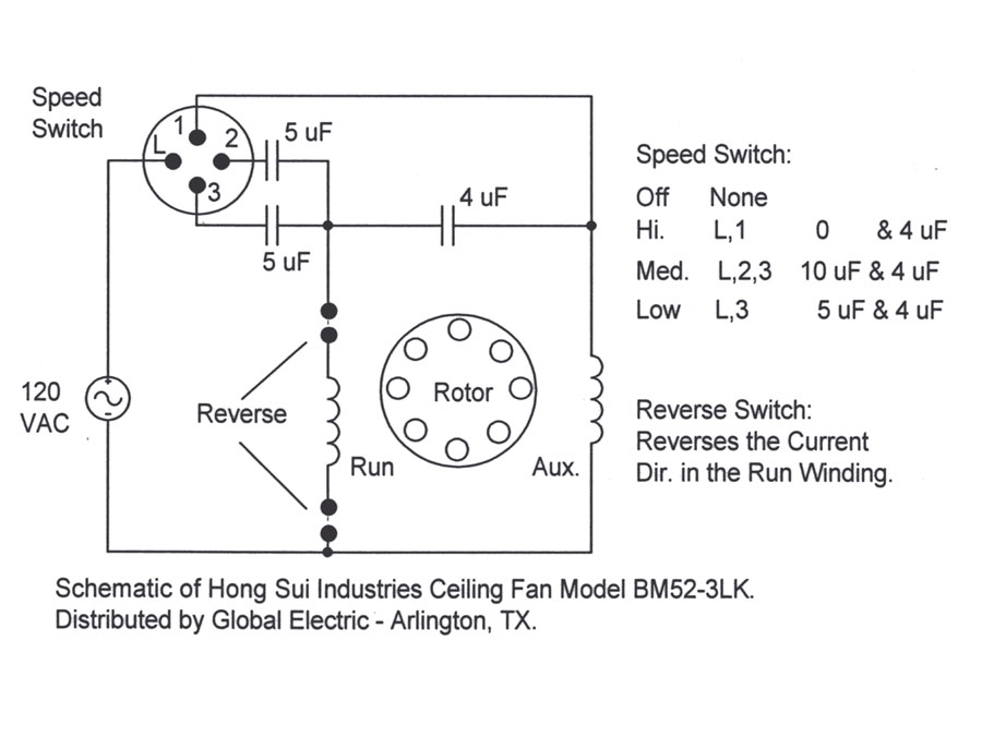
Important: this post, the problem, the functions, the graphs, the spreadsheet, the replaced speed switch problem, the discussion, the installation, the final summary, and any other section or concept I’ve not mentioned: all apply only to one particular schematic, not reproduced on this page, but a likely candidate was found, a simplified three-capacitor ceiling-fan schematic, which uses one particular speed switch. If the fan uses another kind of speed switch from those two discussed herein, then my system of sorts won’t work as presented, at least not without some changes, possibly minor; or if the fan has two capacitors for three speeds, or is wired to any other schematic, my system of sorts also won’t work as presented.
It’s also important to understand that the chain-pull speed switch is altogether different from the reverse switch. For a short discussion of the DPDT reverse switch relative to the simplified schematic, something I overlooked when originally writing this post, please see comment #15, there are some links to generic yet detailed reverse switch schematics.
Clearly, it is easiest and fastest to replace any blown capacitors with precisely equivalent values the factory used, if they are available; the same seems true of switches. This exact or precise replacement advice is, at the time of this writing, consistent with the vast majority of webpage ceiling fan FAQs easily found using search engines.
I must listen to the beat of a different drummer.
. . .  Introduction continued
After learning or realizing speeds could be altered, I decided that two fans in rather small rooms would be preferable running at somewhat slower than factory speeds, so making an informed guess as to which possible microfarad value capacitors to purchase took some study and spreadsheet creation time — quite a bit of time if one also includes writing about it. Not only did I want two of the fans slower overall, I particularly wanted to change medium speed’s relationship to high and low, from being rather close to high, to being closer to low, or at least be solidly in the middle judging from the breeze created. It’s possible to increase or decrease the range or distance, or fan-speed RPM variance, from high to low, and I decided I wanted less variance in those smaller rooms, high speed moved the air too fast and wasn’t used, and I wanted low to be slower.
Consequently, I needed to devise my own ideas regarding how these capacitors worked in the motor’s circuit for speed control purposes, and I needed to do this with all due haste, without becoming an electronic engineer, without spending years attempting to unravel the highly-complicated theories of hundreds of thousands of highly-precise past & present academics en masse, and without spending additional money beyond capacitor-module replacement. Fortunately, I was able to assemble other great web writers’ brief ideas, even if they were only presented in bits and pieces, into a system of sorts that allowed me to alter ceiling fan speeds by altering the capacitors values without needing to buy every available capacitor value and try them out by installation, followed by removal, and replacement with another, etcetera, until by sheer luck a combination of microfarad values were found that provided satisfactory fan speeds.
It’s rather ironic to remember that in my prior post I wrote I wanted a “quick and simple” solution.
This posting is intended for my own future reference. It has been through a number of revisions, as more information and further insights were added, at the time, to the only existing section which has now become the reorganized discussion section, the original post’s overall structure became more confusing, so a final (ha ha) restructuring seemed in order, and to some degree, is presented in the reverse order that it was originally written for inclusion. While the functions and graphs were one of these items added near the end during later revisions, included after I’d had several light-bulb moments due to the actual writing process, the spreadsheet was one of the first, and it uses the same functions or formulas. Much of the information presented is potentially confusing, some math is involved, and there are no guarantees that even the concept of my system of sorts has any basis in accepted or correct electronic theory, though it did work for my purposes.
Read at your own risk.
The nitty-gritty is found in the final summary at the end of the post, and should be accurate to the best of my knowledge; the replaced speed switch drawing of the chain-pull switches’ power-routing logistics should not be skipped, since there are multiple variations of switch logistics. Tracing the capacitors’ wires to the speed switch is also a good way to label capacitors one (C1), two (C2), and three (C3).
If you are formally trained and experienced in electronics, unlike myself, and you happen to read this post, any suggestions for improvement, or even a “You’re nuts!” followed by ‘the why’ rationale, would be appreciated. The spreadsheet calculations do seem to have one issue that I cannot resolve at this time, it’s explained below, and there may be others. Terminology I’ve used may not be what is typical when used by specialists.
The Problem

It’s always nice to know what one blown capacitor module looks like. The deformation on the side is quite visible, but there’s some on the left front as well. It’s understandable why, for ceiling fans, the capacitors are encased in injection-molded plastic and pourable epoxy. Unfortunately, the only way provided by the manufacturer to remove the module was to cut the wires. After the low-speed capacitor blew, this particular module continued to work on two remaining speeds before removal for well over a year of intermittent usage. It seems there are still two good capacitors in it.
Another module with a blown capacitor showed less-obvious case damage, but the purple wire was quite scorched, it’s color significantly darkened for about the first 1/2-3/4 of an inch measuring from the black epoxy. Apparently, before blowing, it seems capacitors get quite hot.
Replacement of the factory’s chosen microfarad values should be easy enough if those precise values are available, but how does one also alter the fan’s speed?
Functions
This section discloses the functions I conceived for ceiling fan speed alteration, after reading, and thinking about, web-based research fully disclosed in my prior post. I thought I could calculate the Capacitors’ Microfarad-Values Difference supplied to the two motor coils, what I have named Coils’ Δ (Δ = Delta or difference) in the tables below, and come up with an abstraction that relates, however imperfectly, to the fan’s speed. The formulas apply only to the schematic I used, though they could easily be altered for other typical ceiling fan circuits if the schematic is known.
These formulas have not been tested for accuracy by precise RPM measurement, but only a cursory, visual one mentioned briefly in the discussion section. Additionally, there is an incompatibility of High Δ to the other Δs, this is also discussed there. There may be and probably are other issues and flaws that I haven’t specifically identified.
However, before listing my functions, Rick made a comment regarding these functions, and suggested alternatives for medium and low speeds. I wanted to advise readers of these alternatives at this sequential point in the text. Presuming Rick’s formulas are better than mine for the intended use, I can confirm that the graphs below, as well as the spreadsheet, will change. I’m leaving the rest of the text as it was originally written, and I remind everyone of the disclaimer (in red text above) that what follows is likely highly flawed.
These are the functions:
High Δ = f(C1)       =  C1
Low  Δ = f(C1,C3)    =  C3    -(1/((1/ C3    )+(1/C1)))
Med  Δ = f(C1,C2,C3) = (C2+C3)-(1/((1/(C2+C3))+(1/C1)))
How do I use these formulas?
Graphs
The graphs were created with Analysis 2.3 beta 3 (I don’t know why the copy I downloaded several years ago is a beta 3 and the latest version is beta 2, maybe the developer is counting down instead of up, or maybe there was a version rollback). I limited all graphs to 2D. 3D graphs just seemed to add another layer of abstraction without adding much additional understanding, and since most of us have had at least some exposure to 2D graphs, they seemed the easiest to understand.
How a 4D graph might look is a curiosity, since one should allow graphing all three capacitors as variables simultaneously, therefore (perhaps) needing only one graph for all effects upon Medium Δ. However, 4D graphs don’t seem to have been fully standardized yet, and in any case they are way beyond my nearly non-existent math skills. Would a 6D graph allow all variables and all Δs to be graphed simultaneously? Oops, back to reality. . . .
All y results are understood as microfarads, just as in the spreadsheet, and all x values are understood as the titled capacitor’s microfarad value. One of the following capacitor microfarad values is assigned as the x variable in all graphs below, and when not so assigned, they’re constants equivalent to one of the factory modules I removed:
C1 = 4
C2 = 4
C3 = 5
 As a higher C1 capacitor or x-value is chosen, y or High Δ increases.
 Increasing C1 to a greater value decreases both Low and Medium Δs.

 As typical C3 values are increased, both Low and Medium Δ increases.
Considering a negative capacitor, if there is such a thing, goes well beyond my purpose of learning how to alter a ceiling fan’s speeds with typically available ceiling fan capacitors, which appear non-polarized, a type apparently expected in AC circuits.

 This is the final effect I’ve graphed: as C2 increases, Medium Δ also increases.
These graphs present visually-based strategies to adjusting fan speeds that aren’t quite as apparent when looking at the spreadsheet. For instance, had I wanted low and medium speeds somewhat lower and either didn’t care if high would be somewhat faster, or specifically wanted high faster, then adjusting only C1 to a greater value, which lowers Medium and Low Δ, may have been all that was needed for the desired lower speeds.
This would perhaps have required buying fewer capacitors, but would have increased the high to low range, could have exceeded the +1 uf warning linked in my prior post which could potentially over-speed the fan, and even if not harmful to the motor itself (the medium speed circuit in one factory setup delivers 9uF total to the same coil that, if the schematic is accurate, C1 feeds when the speed switch is set to high), would likely have greater stresses on the ceiling mount and centrifugal forces on the blades, and potentially could be quite dangerous. In addition, faster speeds probably correlate to higher power consumption.
But I didn’t want high speed faster. . . .
Spreadsheet
I used Calc, which is downloadable from OpenOffice.org, to calculate the coils’ capacitor Δs: Ceiling Fan Capacitor Calculation spreadsheet. Generally, it’s better to first save Internet-sourced files to the computer’s drive, then scan for viruses, both before opening the file. I did scan it before placing it on the server and it was clean at that time, but there’s no guarantee it’s still clean. Don’t forget the disclaimer!
Be sure to note there are two tabbed sheets included, the formulas are useful only for fans that use the wiring logic of the schematic I used, though it’s easy enough to alter the spreadsheet’s formulas for other ceiling fan wiring schemes if the reference link titled “Capacitors in series and parallel”, located in my prior post, is understood, and an accurate schematic of the fan is available.
How do I use the spreadsheet to alter speeds?
The spreadsheet does not attempt to convert the capacitors’ values into rotational fan speeds. It seems mostly useful for making a best guess regarding possible replacement capacitors’ microfarad values for speed-alteration purposes.
After some spreadsheet study time I chose 3uF, 2uF, and 4uF single capacitors to replace each factory module for the two fans I wanted to slow. The first fan’s speeds were about what I expected (the formulas seemed to have worked for their intended purpose), but the second fan moved much slower on the medium-speed setting, and no matter what combination of connections or reordering were tried, one speed was always too slow.
The Replaced Speed Switch Problem
This is apparently another method to lower only medium’s speed, discovered by error. I had thought these two fans were identical, but the speed difference was found to be due to a speed switch I had replaced in that particular fan several years ago which routed power through the fan’s capacitors slightly differently, and which I had forgotten about having installed.
The replaced switch fan, when the speed switch was set on medium, routed power through only two capacitors, Med Δ = f(C1,C2), instead of the factory’s design of all three, Med Δ = f(C1,C2,C3), and my spreadsheet formulas hadn’t been intended for that logistic. I recall that after the switch’s installation some years ago, the wiring going to it had to be reordered so high was on chain pull one, medium on pull two, and low on pull three. I also recall simply being happy enough that its prior broken switch was replaced and that the fan seemed to work again with three reasonably acceptable speeds, even though I didn’t understand why medium speed had slowed down.
 Here’s how the original and replacement switches work, presented in semi-schematic form that is accurate for the two fan switches we have according to continuity testing. Note the differences, especially with regard to the column under “Medium”. The innermost circle and four dots represent potential connection points, lines between those dots indicate connections or continuity. Moving outward, the next circle with numbers indicates printing on the case of the switch housing near each wire insertion point, and the area just outside any circle may indicate the color of the factory wire connected to it.
If the fan has different speed switch-to-capacitors-to-motor coils’ logistics, then the coil difference formulas won’t necessarily work without some rather minor modifications, nor would these switches necessarily work.
Ultimately, this project has also taught me that it doesn’t matter a great deal what kind of switch the fan has provided it’s all wired logically. I’ve even conceived of how to adapt our fans’ inner wiring to the two-capacitor, three-speed ceiling fan wiring scheme, but I don’t have one of those kinds of switches to play with, so I think I’ll let that conception pass, for now, but trying and testing it could shed further understanding upon the spreadsheet issue explained below. Why buy a switch if one isn’t needed? But it’s nice to know that if it was the only kind of switch available, with sufficient forethought and rewiring time, perhaps additional capacitor microfarad changes, it could probably be made to work pretty much the same.
Discussion
I used the spreadsheet by first inputting the values of the factory capacitor (which should be printed on each capacitor case), noting the calculated answers, and then comparing those answers to other possible capacitor combinations’ answers. I then used simple if-then formulas, such as testing for medium values being lower than low values, then sorting the answers and making appropriate row deletions, as well as coloring and cut & paste features quite a bit to pare down the vast number of potential choices. However, there is an even simpler way to make these decisions, but I didn’t know what it was until after writing out, then revising, what I had learned, an iterative process which seemed to provide further insights.
One issue to be aware of is the need to get each capacitor’s respective value into the appropriate C1, C2, or C3 spreadsheet cell: wire colors, where those wires go, and schematic diagrams are all useful for this, but the single best way to locate and identify them seems to be following the wires to and from the chain-pull speed-switch wire-insertion number (switch terminal).
| High | Med. | Low | ||||
| Factory Switch |
C1 | C2 | C3 | Coils’ Δ |
||
| Factory Module |
4 | 4 | 5 | 4 | 6.23 | 2.78 |
| New Capacitors |
3 | 2 | 4 | 3 | 4 | 2.29 |
| Approximate percentage change |
-25 | -35 | -18 | |||
The spreadsheet numbers claim I have reduced High’s Δ by 25%, medium’s Δ by 35%, and low’s Δ by 18%: I don’t know how well Coils’ Δ correlates to actual fan speeds, but it seems to roughly agree judging by visually observed speeds. Since high was reduced more than low, I’ve narrowed the high-to-low speed range; also, since I’ve lowered medium the most, I’ve brought it closer to low relative to high. This is about what I wanted to achieve.
Skip all the rigamarole and jump to the next table entry.
One identified spreadsheet issue is seen in the light green column, which represents high. This column’s answers cannot be directly compared to the answers in the light blue columns: a lower value in High’s Δ may result in a faster fan speed than a higher value for Med’s Δ, or the next one which represents Low’s Δ. For example, using the data for the factory module, the “4” is faster in the high-speed circuit than “6.23” is in the medium-speed circuit. However, it seems the two light blue columns can be compared to each other, these represent “medium” and “low”, respectively. It is not clear whether medium and low values associated with one high Δ (in the same row) can be compared to other medium and low values with a numerically different high Δ existing in their respective rows, though that is a presumption I made both at first and in the table above.
C1 entered values are included in the function or calculation of medium and low Δs of the same row, as well as simply echoed for the high circuit. Since a shorted or solid wire apparently approaches infinite capacitancesee prior post for reference link, it’s possible it’s in error, then if one coil is supplied with infinite capacitance, and the other with C1’s value, then high Δ is the difference between these two coils. I’m not sure how to mathematically deal with the infinity concept correctly, there are several possibilities that I can conceive, two of which are ∞-C1 or C1-∞, but how does one convert that into a practical number unless infinity and zero can be substituted for each other on the number line?
One potential rationale for the error is that C1 feeds one coil in the high circuit, in the other two circuits, it appears to feed the other coil, judging from the schematic. Perhaps these two coils have different angles with respect to each other and or the motor’s magnets. Anyway . . . if high’s value could be compared to the medium and low circuits, then the high to low range could easily be calculated, and a spreadsheet formula such as (med-low)/(high-low) could give an accurate abstraction of the relationship of medium to high and low, and which could also help to filter the many possible capacitor combinations down to a smaller subset of preferred values.
It seems the best way to use the spreadsheet to select capacitor values, for the particular wiring schematic under discussion and using the factory speed switch, is to choose the high value that results in an acceptable high speed either by noting the spreadsheet value’s percentage change, installing that value capacitor and testing the high speed, or a combination of both. Then, keep only those rows that include that particular high column’s capacitor value, deleting all the other rows that have different values in that same column; then select low speed values only from those remaining rows, and thirdly or lastly, select medium speed capacitor values. My reasoning for this is due to the fact that the high speed circuit uses only this one single capacitor (C1): the other two slower circuits also use this same capacitor in addition to others, therefore, all circuits are dependent upon C1 to one degree or another. Following this reasoning, the slow circuit uses two capacitors, C1 and C3, so it seems selection of C3 is the next logical choice. Finally, medium speed uses all three capacitors.
Another way of stating this is: if medium speed is unsatisfactory, changing capacitors C2, C3, and/or C1 will change medium’s speed, but changing any capacitor other than C2 will also change other speed settings; if low speed is unsatisfactory, changing C3 and/or C1 will change low’s speed, but changing C3 will also affect medium speed while changing C1 will affect all three speeds; and finally, if high speed is unsatisfactory, changing C1 will change high’s speed, but changing it also affects all other speeds. Thinking of it this way is somewhat more complicated than as-simple-as-it-can-be construed.
This is also, apparently, determined from the formula functions:
High Δ = f(C1)
Low  Δ = f(C1,C3)
Med  Δ = f(C1,C3,C2)
In the search for the perfect combination of fan speeds, it may be necessary to compromise to some degree, due to space limitations and capacitor values that are available, though if the capacitors are small enough and there is enough space for more than three, then by using multiple capacitors in series and or parallel, and substituted for each single capacitor in the basic schematic, speed choices would seem quite numerous and adaptable.
With one set of medium and low Δs, I found that multiplying them by “4” resulted in a close prediction of the fan’s respective speeds over a 10-second time period, the speeds that in some cases I could count visually by timing with a stopwatch. However, that relationship did not hold with some other capacitor values I checked, so I concluded I either made an observation error or the relationship of coils’ Δ to fan’s RPM, if one exists (it certainly seems to), is not linear.
| Factory Switch |
C1 | C2 | C3 | Coils’ Δ |
||
| Chosen Caps |
3 | 2 | 4 | 3 | 4 | 2.29 |
| Change Order |
3 | 4 | 2 | 3 | 4 | .80 |
With the factory speed switch, I could change some of the fan’s RPMs simply by changing the wiring order of the existing capacitors. Whoever first designed this type of circuit was quite clever.
Observation has informed that with this circuit design, and this particular set of three capacitors, a .80 low Δ is much too slow to be practically useful: one might mistake this speed for the ‘off’ switch position if one is in a hurry. It’s still handy to know that simply by changing the wiring order of existing capacitors of differing values, fan speeds may be altered.
| Replaced Switch |
C1 | C2 | C3 | Coils’ Δ |
||
| Chosen Caps |
3 | 2 | 4 | 3 | .80 | 2.29 |
| Change Order |
3 | 4 | 2 | 3 | 2.29 | .80 |
With the replacement speed switch, the same reordering results in a different, less useful outcome. However, from a capacitor selection standpoint, this logistic is simpler to understand.
| Switch type |
C1 | C2 | C3 | Coils’ Δ |
||
| Factory | 3 | 2 | 4 | 3 | 4 | 2.29 |
| Replacement | 3 | 6 | 4 | 3 | 4 | 2.29 |
To make the replaced-switch fan have the same Δs (which seem to correlate to speeds) as the factory-switch fan, it’s necessary to change one capacitor to a different value.
What does Coils’ Δ mean?
Installation
 A removed and fully-functional module is seen next to the new and, except for the 4uF in the front, lower-value single capacitors on the right (I bought these capacitors from one of the suppliers listed in my previous post which was titled: Ceiling Fan Capacitor Woes). The reason the module is both still functional and removed is the fans I wanted to slow were not the fans with blown capacitors. It was my intent to move these good modules to the broken fans, to minimize the number of capacitors purchased. However, there was another problem, the factory module had five wires, these replacement capacitors had six wires.
 When I wired the capacitors into the fans, I used male and female insulated crimp connectors. I thought this would make the process of
switching their ordering, or future replacements, that much easier. The harness simulates the schematic printed on the factory’s modules. There may have been a cleaner or simpler way to do this, but this was what I happened to think of at the time.
 With respect to the mini-harness, I was worried about the wire’s insulation, so I additionally wrapped it with electrical tape.
 This is a photo of the factory switch fan’s control housing or case with the new capacitors installed. Some of the model numbers on the speed switch can be seen. The reverse switch is also partly visible.
Final Summary
 Pulling it all together, and in spite of some initial confusion, spreadsheet issues, seemingly needless complications, and errors, this is the final installation outcome for the fan with the factory switch. Does it look familiar?
To summarize the ordered and incremental steps to alter the fan’s speeds, with respect only to the simplified three-capacitor ceiling fan schematic, using the factory switch to identify each particular capacitor (C2 and C3, C1 is the sole remainder), then:
- Set high speed first by altering C1’s value if high speed is unsatisfactory. Changing C1’s value changes all speeds.
- Set low speed second by altering C3’s value if low speed is unsatisfactory. Changing C3’s value also changes medium’s speed.
- Set medium speed last by altering C2’s value if medium speed is unsatisfactory. Changing C2’s value only affects medium speed.
How much does changing the microfarad values affect other speeds?
Writing this post out sure helped me to understand how the capacitors affect different speeds. Remember, I do not advise you to repair or alter your own fan!
It bit complicated to alter or repair you own fan since it is bit dangerous you will do the wrong way it will cost short circuit . Anyway its good to note that every ceiling company doesnt bother to add it off to there products but your articles are really detailed I will present this one to some students taking up repair am pretty much sure they would get something with it.
“This posting details knowledge I’ve gained in the process of successfully replacing ceiling fan capacitors that had blown, but additionally, understanding of how to alter the fan blade’s revolutions per minute (RPM).” – Fantastic. Only when we get a problem and we try to find a solution we get lot of information related to it. What a Great informative Story!
The Light kit below the fan says Airflow by Casablanca. My house was built in 1994. Builder installed these fans.
According to the sticker on the top of my white fan it reads: E81964 Model F252, 52″ Four Seasons Fan. No: 036877
The Pull Chain broke and the fan was on all day. I turned off the circuit breaker and removed the old switch. It had 3 wires going into it: PINK, YELLOW and GRAY.
I do not remember where these wires went into the Switch. My Switch has L, 1, 2, and 3 written on the face. It is a JIN YOU Switch.
Do you have any experience in this model Fan? If so can you tell me the original configuration of the colored wires to the L,1,2,3?
I contacted Casablanca and the only records they show for a 3 switch has Green, Brown, Black and Grey going into the Speed Switch L, 1, 2 and 3 respectfully.
I spoke with some other repair guys and they told me that if my switch has L,1,2, and 3 that there should be four wires attached to it. But I double checked and I only removed 3. Pink, Grey and Yellow?
Any Help or other resources would be greatly appreciated.
Thank you,
No, and no. I wouldn’t want to speculate. Sorry I can’t be of more help.
It sure would be handy to have the schematic, wouldn’t it?
ceiling fan wires colored yellow,purple,black and orange. Replacement switch has markings L,1,2,3, and is a chain pull type. help with proper connection
The colors of the wires needs to be noted before disassembly. One way to do this is to take pictures. Another way is to write it down, any colors and where those wires go, in your particular fan, similar to how I showed above with my fan here and here.
Link to return to article.
The only other way that I’m aware of to figure the puzzle out is to backtrace the colored wires to their components, this presumes you have an accurate wiring diagram and know how to read it, upon which the proper connection point should then become obvious. In the absence of a wiring diagram or schematic, then one can be drawn by backtracing all the wires to all their components. This is quite time consuming, but I’d guess it can be done.
The repairfaq.org link in my prior post claimed that manufacturers are under no obligations to keep a standardized color coding for their internal wiring, that they pretty much use what wire they have on hand. I don’t know if it was an accurate statement, or not. They have additional suggestions for what to do when you’re not sure what wire goes where, and I’d guess their method would work, I used a variation of it myself years ago with the forgotten switch replacement described above.
In any case, it’s important to always note where wires go BEFORE disassembly and record that information, then you can refer to that record during reassembly.
Good luck, and don’t forget the disclaimer!
Ihave a Home Pride ceiling fan with a blown capacitor. The module is a
DY10. I see Switchco http://www.ceilingfanparts.com/images/pcboard.htm has one for 24.95. Although mine does not have the
simple plug but press in wires ( press in pierces the insulation and makes
the connection). I was wondering if you could just bypass the whole board
and let the motor run full speed then control the fan with an outboard
speed control. Not sure exactly what kind of motor it is.
It dawned on me that the Home Pride fan motor is probably an induction motor
and requires the capacitor to start and run – so removing the circuit
board is not an option.
Al
Any ideas or suggestions finding replacement ceiling fan 4-speed on/off chain pull switch. Chain fob has name Galleria on it. The chain broke just as it enters the body of the switch. The round, 5-wire switch has the name ‘JIN YOU’ along with; 3A 250VAC, 6A 125VAC, and PB108 and E70469, Taiwan.
Any help,or suggestions will be appreciated.
Thank you,
Leonard L. Roderick
[personal contact information deleted by admin]
Leonard, I believe that you have at least two choices, one is to replace the switch (if you can find a replacement), the other is to (possibly) repair the broken chain pull by disassembling the switch and installing a longer replacement chain.
I’ve repaired broken chains in 3-speed switches more than once, however, they (sometimes) seem to break when the switch is getting harder to pull due to some type of age and/or wear within the switch, so replacement of the whole switch w/chain is probably preferred (depending upon availability).
Good luck.
I NEED A CAPACITOR AC 250 VOLTS 3.75 UF +_ 5% # ON CAPACITOR IS E143782 HAS 2 WIRES RED WHITE I SAW SOME ON YOUR SITE ON THE RIGHT SIDE OF ONE PHOTO. IT SHOULD WORK, I THINK. MY OLD ONE IS A RECTANGLE 1 IN. H 1 1/2 W 1/2 DEEP FRONT TO BACK . CAN YOU HELP ME GET ONE OR MAYBE 3 SO I CAN FIX MY FANS I HAVE 4 OF THE SAME KIND AND ONLY 1 HAS BURNT UP THE CAPACITOR. PLEASE HELP ME IF YOU CAN THANKS DAN NTE CFC-4 LOOKS LIKE IT SHOULD WORK WHERE CAN I GET SOME LIKE THAT OR SOME JUST LIKE MINE RECTANGLE SHARP CORNERS PLEASE LET ME HEAR FROM YOU
THE POST JUST ABOVE IS MINE. I NEED THE SAME CAPACITORS THAT YOU HAVE A PICTURE OF 3.75 UF +OR- 5% UP TO 370 V AC IS OK I HAVE BEEN TOLD . MINE SAYS 250 VOLT. IF YOU STILL HAVE THEM HOW MUCH WILL THEY COST ME .?? 2 WIRES FROM EACH CAPACITOR RED WHITE. PLEASE LEAVE ME A NOTE ON E-MAIL AND I WILL BUY 3 FROM YOU
THANKS
Hi Dan,
My prior post titled “Ceiling Fan Capacitor Woes” lists several suppliers of those capacitors, included in that list is the supplier I purchased the new ones pictured above. I have no business relationships with any of the suppliers, I simply used a public search engine to find them.
I have a 52″ Cieling Fan in my living room, and all the wires accidently got disconnected from each other. And I do mean al the wires.
I have 9 different colors of wires and I have no idea where they get they go, to the switch – forward and backwards motion, (I did have it working on reverse on all three speeds but when I switched over to go forward it would blow thee circuit breaker everytime. I have been working on this all day and can bot seem to get aby where with it, And I do NEED My ceiling fan operating!
Can anyone please help me!!
Veronica, I hope this is humorous: With all the broken wires, it’s now a PUZZLE(!) and subject to my time wasting disclaimer!
My first instinct with things like this is to get a schematic. The schematic used in the above post may or may not match your fan’s wiring, but if your fan is similar to mine, then Be Aware that schematic has an idealized or simplified reverse switch. It’s logistically accurate but doesn’t show all the wires or the switch’s terminals used to achieve that logic!
My ceiling fans’ reverse switches of six terminals each are known as a ‘double-pole, double-throw’ or DPDT switches. They are commonly used for polarity (DC) or phase (AC) reversal.
There are a number of generic (not specifically for ceiling fans) DPDT motor-reversal switch schematics online, here are a few of them:
– Motor Reversing DPDT switch wiring that appears here.
– Sherline has published directions for reversing the motor direction on some of their machines, and it includes a nice image of a DPDT switch in a similar motor-reversal scheme.
Sometimes the input and output wiring are reversed relative to each other, as the next images show versus those above:
– Wiring for DPDT reversing switch appears on The Electronic’s Club page.
– The next image URL —> hzzp://www.1728.com/dpdt.gif <— (it’s not a live link due to request of site owner, sorry, just copy and paste it manually into your browser and change the “zz” to “tt”) That image appears on a Basic Electricity tutorial page (you’ll need to scroll around a bit to find it).
Quick link to return to article.
If you find the puzzle becoming too frustrating or time consuming, you could decide to buy another fan, but it reads like you made some significant progress with your unexpected(!) repairs, though the puzzle(!) is not yet fully completed. It helps to write down what you do, the successes and the mistakes, sometimes a pattern emerges, or sometimes just eliminating what doesn’t work helps.
Good luck!
The error is in you formulas for the equivalent capacitance. I have shown corrected formulas andsome results below. You were trying to make this more complicated than it is. I uses 4uF,6.5uF and 6.5uF respectively for the values to show difference in the 2 formulas.
Your formulas
High 4.00 = C1
med 9.94 = (C2+C3)-(1/((1/(C2+C3))+(1/C1)))
low 4.02 = C3-(1/((1/C3)+(1/C1)))
Corrected formulas
High 4.00 = C1
Med 3.06 = 1/((1/(C2+C3))+(1/C1))
Low 2.48 = 1/((1/C3)+(1/C1))
for your cap values of 4uF,4uF,5uF
Correct formula
High 4.00
Med 2.77
Low 2.22
For your cap values of 3uF,2uF,4uF
Correct formula
High 3.00
Med 2.00
Low 1.71
Put these in your spreadsheet and give it a try.
You can see for each speed decrease the capacitance decreases. This also changes all your graphs.
Also using you switch diagram:
As C1 increases all speed increase.
As C2 increases only the medium speed will increase.
As C3 increase both the medium and low speed increase.
Hope you find this useful.
Hi Ken,
I happened to trip into your blog site, reading your project diary.
You are lucky not to get hurt for the wrong cause.
Refrain from mimicking from ‘blogs’ and ‘google-searches’.
DO NOT follow the above plan.
My friend brought a ceiling fan with light kit on it and somewhat the pull chain box is not goin by speed 1,2,3 it goes from 1 to off and 1 then off, i took the light kit off to investate the problem and i see 4 wire pull switch with a plastic part broke off. (somone must be pullin too hard) but two wire came off of this pull switch box label’d L,1,2,3 wires are black orange purple yellow
as i see L was orange and 3 was black the yellow and purple was hangin out of 1,2 so that was just a diagram for black on 3 and orange on L. unfornally i have another ceiling light in other room i am goin to take that off and take a look for proper wire diagram for this switch that came off to put it back in, i super glue the plastic that broke off and reinstall it.
Hi Rick! Thanks for thinking about it and offering an alternative!
I’m sorry it took me so long to get back to you, I was preoccupied with another maintenance project for a couple of months, and couldn’t spare the time to sit down and think or meditate about your formulas. You’re probably long gone due to the time lapse in answering you, but just in case you happen to drop by again….
Sure, but just looking at your chosen capacitor values my question would be whether those values resulted in a medium speed that actually is faster than HI when measured at the fan? Going from memory, as this project was completed some time back, I wondered for awhile whether F(c1) = 2C1, it seemed approximately correct when I was testing against fan speeds visually, then I discarded that idea when some issue, that I no longer recall the specifics of, presented itself.
In your formula, “Low 2.48 = 1/((1/C3)+(1/C1))”, you appear to be ignoring the difference (what I termed delta), and any effect of the Aux coil. You are using part of the same formula that I used for the “leg of the circuit that goes to the Run coil” without also accounting for the energy’s effect on the Aux coil, which my differencing tried to account for.
In your formula, “Med 3.06 = 1/((1/(C2+C3))+(1/C1))”, it appears you’ve used the same pattern as with the low, once again ignoring the effect of energy on the Aux coil.
What I don’t understand about your formula implementation is that with Hi speed, what I conceived as a difference or delta seems to result in C1, the same answer you came up with. I see the Aux coil gets energy (or whatever it’s correctly referred to as) without the influence of a capacitor, while the Run coil gets energy after it “goes through” C1. Therefore, the difference of the two coils (that act on the rotor) is simply C1 (or possibly the absolute value of -C1). Since your formula for HI seems identical to mine, it’s not clear whether you conceptually differenced the Aux coil and the Run coil, or did not.
The pattern you’ve used for the formulas for both LOW and MED seems to ignore any effect of energy on the Aux coil, whereas all of mine attempted to account for an effect on the Aux coil.
Why are your formulas solely concerned with the Run coil(?), or alternatively, why are your formulas ignoring the energized AUX coil?
I’m not trying to be difficult, I know there’s some kind of error in the formulas I used, I wrote something about struggling with infinite capacitance (which seems only an issue in my HI circuit formula), but I’m just trying to understand your underlying rationale :-)
Rick, now I see why. I was never happy with the formula for HI speed for the reasons explained in the original post (and the fact I derived it, in part, intuitively, which I mistrust), however, your formulas for medium and low speeds seem to follow the same logic. It does make more sense that all the formulas follow the same logic, as that probably eliminates the need to calculate a percentage change for each speed.
I’m unlikely to make any changes to the main post, though I probably should add a link to your post at some point early in the math portion, to advise others there’s another way to conceive of this.
Thanks for taking the time to investigate and comment.
Hi Ken, Thanx for a well thought out presentation. Originally you alluded to two items that got lost in your endeavor. Temperature and energy consumption. Can you comment on heat increase/decrease your capacitor change made to the capacitor and/or overall unit. And can you place an in-line amp meter in the circuit to determine increased/decreased energy useage per given fan speed. It may be possible to overheat the capacitor or the motor winding if a large capacitor value change is made. It may also be possible that even though the fan may actually run slower it may be consuming more energy and therefore should perhaps run at the original speed but utilize shorter blades or a flatter blade angle. Thanx again for all your info. Dave
Hi Dave,
Thanks. Dave’s comment: “…and therefore should perhaps run at the original speed but utilize shorter blades or a flatter blade angle.”
Changing blade pitch or angle changes the blade or shaft RPM, so what do you mean by “original speed”?
It appears to me the capacitors alter the apparent power output of this particular motor’s winding design. This RPM change is testable. It is repeatable. It also appears to be calculable. When I write “power output” I’m using the phrase loosely in an English sense, not strictly as a specialist may understand the term. A better loose term may be torque, though I’ve never seen that applied to commonly marketed and retail-level electric motor specifications, HP or horse power seems more commonly used on the size of most electric motors I’ve looked for in the past.
Thought continued…
The blade-pitch/RPM-change is easy to test on the low speed setting as it can be visually tracked by the eye and timed with a stopwatch. It seems this would also be true if the existing blades are shortened, but this is not as easy to test, as it makes a permanent change to the existing blades’ dimensions and surface area, and could become rather expensive if shortening them did not result in the desired outcome, to say nothing of refinishing expenses and time.
I’d rather have longer blades moving slower, as this should decrease the turbulence created by our existing fans’ blade design. Flattening the blade angle such as you’ve explicitly suggested, will increase RPM, and possibly increase associated turbulence of our existing blades, though flattening the pitch would seem to offset turbulence potential to some degree.
There’s also a deeper level of “speed” that relates to volume of air movement with each single revolution of the fan’s blades on each respective switch position. As blade pitch is changed to to a smaller angle relative to the plane the blades rotate upon (which would seem to move less air with each single revolution), the fan blades’ RPM appear to speed up, suggesting that RPM or pitch (when each is considered singly) is not the only factor relative to the amount of air in the room moved. Reducing the pitch angle seems somewhat similar to shortening the length of the blades (and keeping blades’ pitch constant). Increasing the pitch angles, or presumably lengthening the blades, slows the apparent RPM, but would seem to move more air with each single revolution, at least up to some pitch angle, perhaps 45 degrees (just a guess) (Upon further reflection, moving it past 45, fully to 90 degrees, then the blade would be centrifugally pushing air away from the fan horizontally, and the ability to reverse the air movement would be lost, as either motor direction would push the air the same way). Back to shallow blade pitches: Turbulence would likely be an additional factor to consider, particularly at higher RPMs, so I’m guessing there’s some mathematical non-linearity herein. Certainly, the blade tips are moving faster through the air than the portions of the blades closer to the motor’s shaft (circumference) at any given RPM.
In addition to changing the pitch of the blades, one could also bend the end of the blades downwards toward the floor some small amount, and a leverage factor may come into play with regards to RPM. For a visualization, imagine a conic shape (versus a flat pancake) with the point of the cone at the ceiling. As the fan blade tips are increasingly moved toward the floor, each an equal amount, the diameter of a horizontal “pancake” slice decreases (“slice” intersects with all equally moved blade tips); another way of phrasing this is the radius (blade tips to the center of rotation) decreases as tips are pulled downward. However, in this case, the surface area of the blade would not change.
So, flow of air in the room can probably be focused or flowed somewhat differently by changing various geometries of the fan’s blades. To greater or lesser degrees and for various reasons, it seems these would also change the visually-apparent RPM of the blades, with one adjustment possibly having a tendency to cancel the other with respect to the total volume of air moved over some fixed time period.
While there are many different ceiling fan designs, often incorporating different blade designs, some no doubt quite high-tech and perhaps a minority of them with low-turbulence design, the fans for the masses such as I could afford were outfitted with simplistic straight blades apparently made of thin plywood. Further, these seem to be the only replacement-blade design available at any cost at mass-market outlets that I’ve seen. Retrofitting a low turbulence blade design is probably not cost effective, as it would probably require special machining of the part they attach to (or custom manufacturing of that part) and which itself attaches to a part of the rotor, and all the associated refinishing that might be required so it looks nice. Additionally, even after the time and expense of retrofitting, the actual breeze created on the various manufacturer-set speeds would still likely need adjustment. So then one is left with purchasing some entirely new ceiling fan at some very high cost given the way manufacturer’s and retailer’s MBAs like to consider “value added” when they price their products (instead of pricing based upon cost of production + a reasonable profit).
My primary objective was to repair the fans’ blown factory capacitors by replacing the capacitors, the secondary objective was to slightly alter fan speeds. The secondary objective came about in the process of looking for capacitors of exactly the same farad values the manufacturer used, which seemed unavailable at the time, and which required some slight value changes when considering the three-capacitors-in-one modules that did seem to be publicly available. The post I wrote above is a documentation of pursuing that secondary objective.
The fuller “story” is partly available in the other post.
Dave’s comment: “It may be possible to overheat the capacitor or the motor winding if a large capacitor value change is made.”
My experience agrees with “possible to overheat the capacitor”: The factory-selected capacitors also evidently overheat and eventually blow with age, some sooner than others. I’d also guess the motor winding will eventually fail.
When one of these capacitors blows (presumably due to age) depending of course upon the circuit that capacitor is wired to, it seems the fan’s remaining switch settings that may still operate seem to slow down RPM. This ‘blown capacitor circuit’ seems to manifest as a factory capacitor change of much greater than -1uF within that circuit on our fans, particularly as the capacitance values and the energy flow are logically indicated by the wires’ schematic representation both going to the capacitors and from them into each respective motor coil, Run and Aux, and are calculated by capacitance formulas. So, it would seem safe enough to slow the fan, as the one-or-two blown-capacitor fans most definitely continue to operate in their reduced-RPM state for extended-time periods without creating any readily apparent danger.
This capacitance-value change also appears as the primary method used to create the three speeds themselves within the existing or fixed motor design as the speed switch changes the routing of energy that goes to the motor’s coils. “Speeds” in this last sentence’s context is possibly not the best word to use, I’m thinking that a better word could be apparent power output, because the coils are moving the shaft or armature that the blades are attached to and which provide some amount of physical resistance to movement, and presuming no other changes such as blade pitch, a shaft RPM increase indicates greater power output, though I’m probably using the term “power” in a non-electronic or loose sense.
It didn’t occur to me to actually try speeding up the fan for the purposes of testing. I’m sure there’s some kind of safe limit somewhere thereabouts, and am guessing this limit also relates to the HZ frequency of the supplied AC power (and the motor winding design) as well as other specifications. This all gets into areas which were very far beyond my primary purpose of replacing a blown capacitor, and secondary one of slightly slowing air-movement volume for comfort. Calculating most of this is beyond my current level of understanding.
It’s my understanding from online research that this design of electric motor, typically used for a ceiling fan, operates in an almost ‘stalled state of high slippage’, a paraphrase of something I read that is difficult for me to decipher. I presume the capacitors slightly shift the sine wave going to one set of coils versus the other set (Run and Aux). I further presume maximum power is found by shifting the waves going to each coil, run and aux, 90 degrees from each other; going farther than that, to 180 degrees, probably electrically locks the shaft and I can certainly conceive how that would create excess heat, however, the *physical position* of the windings to each other may already do some or all of this angular shifting. I can also conceive how increasing the power output, by increasing the speed the shaft wants to run at by increasing the phase shift going to the two coils, could increase heat. I further presume that at maximum power or torque (whatever phase shift is found to create maximum power) applied, RPM can probably/possibly be altered by changing the frequency of the electric AC powering it, possibly to some degree the voltage (a different mechanism presumably changing the strength of magnetic field), though for the purposes of a ceiling fan, that seems like awfully fancy and expensive circuitry for no reasonable purpose. All of this would undoubtedly alter the heat output due to various changing variables, including the load placed on the motor. In short, I have a lot of *unanswered questions* regarding the operation of this type of electric motor under various operating scenarios, many of which would likely never apply to its usage as a home ceiling fan. My guess is that these motors can be used for a lot of different purposes, but they would seem to require AC power, which limits their usefulness for DC operation, without a conversion of the power to sine (I wouldn’t choose square wave, though it might be useful for testing on a bench, presumably it would be noisy. I see an advantage to phase shifting with sine as it ramps gently up then back down, rather than with square’s abrupt change of polarity, and getting into conceptions of pulses). It could be revealing to hook them up to some DC batteries, and build a power supply that converts to AC and alters the phase shift going to the RUN versus the AUX coils, and which power supply additionally alters the frequency for the purposes of testing — just to play around, of course. I haven’t tested *any* of these ideas, beyond the observation that changing capacitor values of from 1-5uF (or was it 1-6uF) changes RPM. Hmm. I wonder whether the motor could be used as an AC generator? IF a ceiling fan can be used as an alternator, then optimum phase shift and other voltage and current specs can likely/probably be backwards derived by turning the shaft and generating power and analyzing it and its two-coil waveforms and their differences. This *backward engineering* would need to be done on a suitably-equipped electronics-bench, presumably including an oscilloscope. IF it won’t work as a generator, it might be possible to make a custom stator to force the issue, or some other trick like powering one set of coils while turning the shaft with another motor and measuring the changes in the other winding. I’d love to try it myself, but as one ages, priorities and goals change, and all of this takes a great deal of time, and for what purpose(?). So, I limited myself to capacitors sold as “ceiling fan capacitors”, from a company and retailer in the U.S. (same power supply specifications), and presume the sales literature was labeled correctly.
Dave’s comment: “Originally you alluded to two items that got lost in your endeavor. Temperature and energy consumption. Can you comment on heat increase/decrease your capacitor change made to the capacitor and/or overall unit.”
No, or sort of no. In regards to temperature, and given that the capacitors are encased in what appears to be epoxy, and further that that material is likely a thermal insulator, measuring the capacitor’s plate temperature would seem a bit difficult. (Or are you making a physics reference with your use of “Temperature” such as conservation of energy or laws of thermodynamics? If so, I couldn’t possibly comment.) I suppose a temperature reading could be made upon the wire coming out of the epoxy, because that is a conductor, though there could be loss of heat or time delay of some kind.
However, two of our repaired fans have been running continuously on low, one on medium or low, since the repair (need to check date of main post) for about more than 1 year, and feeling for heat at the top of the motor cases doesn’t suggest “heat”: The case feels “cold”, and when momentarily stopping the blades movement (leaving the switch in it’s run position) to stop the movement of air, there’s no readily felt convection of warm air rising from the case.
Dave’s comment: “And can you place an in-line amp meter in the circuit to determine increased/decreased energy useage per given fan speed.” Related comment of Dave’s “It may also be possible that even though the fan may actually run slower it may be consuming more energy…. “
I did not measure that, it didn’t occur to me after spending the far-too-much time I did trying to figure all the the stuff in the main post. I just wanted the fans fixed at that point of time consumption, and decided to publish what I learned so hopefully some others won’t have to spend quite as much time as I did to understand how using a generic ceiling fan capacitor that is generally available but of a slightly different value might change the fans operation after installation. Anyway, your thought of measuring is an interesting test idea, and I believe it would be easiest to perform with a ceiling fan on a bench and the meter set up to measure the power entering the fan, where it’s typically installed to the electrical junction box (house wiring). I’d guess the blades would need to be attached, and the “bench” would need to also simulate the airflow that occurs in it’s installed state. I never removed ours from the ceiling for the above described capacitor replacement, nor did I intend to.
The house’s electric meter could possibly be utilized over some period of time to similar effect without removing the ceiling fan from the ceiling, but it didn’t occur to me, and has problems of its own such as the need to assess other points of electric consumption within the downstream electric distribution, particularly cyclic ones.
I keep thinking about measuring it now. I guess it’s easy enough, the amperage is probably low enough that it wouldn’t blow a test meter, and it does seem, from looking at the wiring diagram, that an inline measurement can also be placed at the load terminal of the switch, or one of the other legs of the switch, something else that didn’t occur to me. It would be kind of nice to know, but there’s no “before” measurement to compare the readings against, except for documentation which could be wrong, so then I’d need to put original value capacitors back in the unit to make such a measurement. Seems like a lot of ado about much of nothing, and for what purpose? Perhaps the next time one of these capacitors blow, and I need to go into the fan’s case for another reason, I’ll remember to check this for curiosity’s sake.
Here’s the basis for my energy statement in the original post, however, my fans’ documentation gives different figures, but the general trend seems the same, that faster speeds use more power, and here I’m using “speeds” as a reference to the phase angles the chosen capacitors create in the respective two windings (or in only one winding versus the other getting a non-shifted phase angle wave).
It seems blade speed correlates with power consumption, though amperage change appears to have a shallower slope at low to med RPMs than med to high. Why bother with verifying this correlation? What’s the benefit in exchange for the lots-of-extra-time spent when the purpose is a ceiling fan repair in a single home? Blade speed seems to tell us a similar thing, as does “feeling the breeze created”.
… If you happen to come back and read this comment, or for anyone else who knows the answer: Does altering the blades’ pitch from some very shallow pitch to some significantly steeper pitch, some pitch or angular amount that results in a significant slowing of the RPM on the low setting (say doubling the amount of time required for ten revolutions, or more), without making any other design changes, result in decreased, increased, or no change, with respect firstly to electric consumption and secondly to the motor’s winding temperature, after continuous operation for an extended time of at least several days?
… My best guess is that increasing the blade’s pitch so that the RPM slows down increases heat in the motor windings. This is based upon something written by someone else whose website I’ve linked to at some point or another in this capacitor replacement project, but I probably didn’t link to the precise URL this info was located on (and who knows if it’s still there), and which I read some time back, before my original post above was written. What I remember was that turning on the power or energizing the coils, and locking the shaft so that it doesn’t turn, seems a method to artificially increase the heat of the motor. Therefore, it seems reasonable to presume that an increase in the blades pitch (or likely a lengthening of the blades) that results in a decrease or slowing of the RPM (indicates increased resistance to movement), would also increase the heat of the motor, though probably not to as great a degree of heat as when the shaft has such a great resistance to movement that it is fully stopped (or “locked”). Further, if this hypothesis of mine has any basis in reality, coupled with the long-time observations of mine in many endeavors, motor heat will probably decrease its total lifespan. Therefore, I think I’d rather decrease the blade’s pitch to a flatter angle (or keep it the same as the manufacturer set the angle), and additionally *slow the RPMs* by altering capacitor values, as a method of increasing motor longevity, in addition to decreasing turbulence, and to decrease CFM.
Okay, I just checked, the ceiling fan guy’s page (search for text “Locked Rotor Temperatures” without quotes) is still there. It’s a great page, but unfortunately it didn’t answer my secondary question regarding how small changes to the capacitor values affect a ceiling fan’s operation.
Ken,
You are a blessing. Thank you for sharing all of your great ideas and the results of your research. Truly splendid!
To everyone that has just arrived at this webpage: Please, Please PLEASE read all of Kens’ other pages before asking a question. He has done such a good job of documenting the internal workings of ceiling fans (or providing links to pages with information) that you will most likely find the answer to your dilemma on one of his pages or links.
For those of you that become nervous or queasy around electricity purchasing a new ceiling fan may be the best solution rather than attempting to repair an existing model.
Keep up the great work Ken!
Hi, I stumbled onto your blog by accident and it has been an interesting read. Its not commercially astute for me to identify what company I am from but I design ceiling fans, motors and controls and supervise their manufacture. I haven’t read everything in detail or analysed your calculations so I only have some general comments.
First of all, be very careful of the voltage rating of the capacitors. Permanent split capacitor motors will push the voltage across the run capacitor a lot higher than the line voltage. Typically when a cap dies due to over stressing they swell and bulge as shown in your pics. Replacing a cap with higher rated voltage is OK. Never use a lower rated voltage.
Second, if you increase the speed a ceiling fans runs at the working voltage across the cap will increase too. So using a larger value cap (speed increase) will also increase the voltage the cap has to operate with.
Third, a lot of fan designs have almost no overhead (margin) between their rated capacitor voltage and the actual operating voltage in the fan. Caps are also graded for useful life (eg. Class C is 3000 hrs at their rate voltage). Running the cap well below its rated voltage vastly increases its life.
Typically the motor run cap (the one is series with the aux winding) is sized to produce maximum torque. Increasing the value more than say 10-20% will slow the fan and cause excessive heat, buzzing and reduced efficiency. Decreasing the value will slow the fan down, but too much will stop the fan from starting to rotate when on low speed.
In your picture above showing the single MD and the three single NTE capacitors, note the MD has 1 x 4uF @ 280V and the other two are 250V rated. The 280V cap will most likely be the run cap in series with the aux winding and rated accordingly. Replacing it with a lower voltage rated cap will possibly lead to premature failure of the replacement cap or a possible fire event if an incorrect type of cap is used.
For most ceiling fans if you disconnect the motor-run cap you can still start the fan turning in either direction by spinning it by hand. It will have much less torque but it will rotate. The reversing switch will have no effect on its direction of rotation.
There are several ways of wiring the speed control switches. The most common way will place line voltage directly across the main winding when on high speed (remember the 280V cap is the motor-run cap and not for speed control). On med speed it will pass through the larger value of the two speed setting caps. On low speed it will pass line voltage through the smaller value cap. The ‘triple’ cap is thus not 3 motor speeds, it is 2 speed control caps and a motor run cap.
Reversing is done by reversing polarity on either the main or aux winding, but not both.
As for blade pitch. Pitch changes will affect the speed and therefore the efficiency and the working voltage across the capacitor. Changing pitch requires changing the number of turns in the motor and the run capacitor value to once again achieve optiumu efficiency. Most fan makers just tip a flat slab at an angle and spin it a circle – there is little science behind it as they just copy one another endlessly. Others (like the company I work for) spend a small fortune on innovative designs and trying to get the best performance for the least energy. We design our products in-house and manufacture in China or Taiwan but as with all things there are no perfect solutions, only best possible compromises.
Hope this helps.
I have a Hunter Westwide II and installed a Lutron Maestro fan control for the fan, and a Smarthome 2486SWH6 Insteon ON/OFF switch to control the light. For the most part it works, the only thing is the fan seems to run too slowly at the highest speed setting, and from the lowest to highest speed setting does not seem to change much. From what I’ve read, I am guessing I need a run capacitor, and it seems like something in the 4.5uF to 5.0uF @ >250v seems to be the ticket. I looked at the web sites listed and found that for about $10 they can be had… however, I checked my local Frye’s Electronics store and found an NTE 4.7uF 250v capacitor for $0.89, could this really work?
Why do the capacitors designed for ceiling fans have such large plastic casings?
Any thoughts or comments?
Thanks.
Anonymous wrote:
Hey, Thanks for stopping by Anonymous and sharing. I was aware of that. You are the first person to comment that they also noted it.
One reason I used those NTE capacitors was that they were publicly available singly. I could not find the MD capacitors at the time, and besides Internet searches this included looking in a tome-sized electronics catalog of several thousand pages. I believe I recall finding a listing for physically-larger “motor-run capacitors” in metal cases (metal cans) of higher-voltage ratings than the NTE (some far higher than even 280V), but their capacitor-case size would not allow installation in the fan’s existing capacitor housing. So then, if I chose those, I realized a need for drywall and painting work, in order to run long wires (if possible) to a metal electrical box where the metal-housing “motor-run” capacitors could be mounted.
I preferred putting them directly in the manufacturer’s case.
The electronics catalog had, perhaps, hundreds of different types of capacitors of apparently different constructions and or materials, evident by names such as ceramic, tantulum, polypropelene, etc., but if it didn’t say either “ceiling fan capacitor” or “motor run capacitor”, I didn’t feel my knowledge was great enough to know which one to select, and it was important to me that the case it came in had containment features.
I do believe at some point I checked the fan manufacturer’s site, but could not find any replacement capacitors listed, I seem to recall that their site, at the time, was dedicated to selling new fans and new fan models, and if they had replacement parts web-listed, that information was buried where I couldn’t find or access it. So I moved on and worked with what was available at the time.
I made my compromises, as well.
At some point in time, when faced with the decision to dispose of the existing fan and replace the entire unit, or to use the NTE “ceiling fan capacitors” that were available to the public, I chose the latter option. Others might choose differently, if they choose to do it at all, and I try to discourage that. My ceiling fans are still running, mostly on “low”, but two of them continuously on that speed (and I love the new lower low speeds I’ve apparently adjusted them to). Occasionally, one is turned up to medium speed for a few hours, and seldom turned up to “high”, but when on high, usually only for a few minutes. Of course, the switch design means a need to cycle momentarily through all other speeds when turning it on and off!
In all these speeds, the “run” winding must be engaged, at least as I understand the schematic.
Regarding the waveform angles, my thoughts are different than yours, and if I had one of these on a bench, and I was younger than I currently am, I’d probably start some testing to understand it a little better, as it’s very difficult to discern where the truth of anything lies these days, when nearly everyone is trying to sell something (but you don’t seem to be doing that). I’m still skeptical, though. It would be interesting to test whether your assertion that completely disconnecting the power to the run winding in fact results in a running fan if it’s hand started.
If so, this could be the same magnetic mechanism that results in higher working voltages, or what I’m thinking of as some kind of spillover. In short, if your assertion is true (and it very well could be), then I’d also want to know why the electromagnets work that way, and that would undoubtedly require a lot more time in analysis than I’m willing to spend (on what should have been a simple capacitor replacement).
Anyway…
I believe the manufacturer’s capacitor (three-in-one units) lasted about 8 years. I’m curious to see how long the NTEs last, I presume maybe not as long, but who knows, maybe it will be longer.
They still seem to be working.
I just decided to Internet search for motor-run and motor-start capacitor, and I see that there are a lot more capacitor choices now than when I wrote this post, some of which, going by the associated images and given case dimensions, would possibly work. Were I to make a similar repair today, I would probably have better options than back when I did the last repair and wrote the original post. It seems that some of the capacitors listed under “motor run” types claim to be of polypropylene construction.
The Internet keeps changing!
Cheapskate asked:
Keep in mind this is only my guess: I figured that the plastic casing, with what looks like filled epoxy, served at least two purposes: insulation and containment. I honestly don’t know if a capacitor can be kept cooler by not insulating it (they seem to get hot before they blow), or by heat sinking it (ignoring momentarily the need to isolate each plate’s energy from a ground or conductive point to avoid a short), but containment seems like a reasonable safety feature.
If containment is one of the reasons that “ceiling fan capacitors†are encased the way they are, then a “motor-run capacitor†may or may not have equivalent containment-safety features.
Multi-capacitor, multi-speed ceiling fan motors with capacitor/winding wiring diagrams.
http://electrical-forensics.com/CeilingFans/CeilingFans.html
Thanks for all the great information. I love doing the research to diagnose problems and this type website is a wealth of information. Thanks again ! Richard
I have a large 20″ Lakewood floor fan. At low settings (three speed) it has(had) quite a lot of air movement. At times it seemed to much. So without thinking about the electronics involved I hooked up a dimmer switch to it. The fan began turning very slowly and the motor heated up quickly. I turned it off. Waited a while and tried it again. Nothing. Lakewood has filed Chapter 7, and no phone or website is available to them to get assistance. Questions: Did this blow the capacitor or is the motor shot? The capacitor does not look melted or deformed. Neither do the motor wires. The capacitor is C51 8 microfarad +/- 5%, Max 70 deg C. I’d like to try to replace the capacitor to see if this corrects /fixes it. IF not any other suggestions. Also where could I obtain a like capacitor. If I want to slow this thing down a bit, what would be a good capacitor to try. Thanks.
The capacitor is 300VAC as well
“Did this blow the capacitor or is the motor shot?” I don’t know.
You mentioned the motor got hot, that indicates an issue. Whether the heat resulted in the motor windings breaking down, tripping a safety fuse of some kind, or something else is hard for me to guess.
A floor fan is probably somewhat to quite a bit different than a typical ceiling fan, and I believe I mentioned above that I’m not an engineer. My ceiling fan “motor” is powered by AC, but is the floor fan “motor” you have powered by AC or DC is a question you need to ask yourself. If it’s a DC motor, but the unit plugs into an AC wall outlet, then the circuitry between the plug-in-the-wall cord and the motor itself is going to be quite a bit different.
I think you have a tracing problem, in other words, find out if and where in the circuitry the power is interrupted, you probably can solve the problem. There are capacitor testers. If there’s power at the motor itself, there are resistance tests (measured in ohms) that can be performed on some types of motor windings using a tool such as what used to be called a VOM or Volt-Ohm-Meter to insure the very-thin and nearly-transparent insulation between the wires hasn’t broken down (possibly as a result of too much heat) and shorted. In all of these cases, it’s easiest if you have a schematic to go from, and it sounds like you don’t have one (a common problem). A top-of-the-line tool is an oscilloscope, this allows you to look at the shape of an electric waveform.
You can buy some types of capacitors at some electronic supply shops. As far as what I found for ceiling fans, my prior post has a list of a few of those suppliers. You could try using a search engine, which is how I found those that I listed.
Good Luck!
Anonymous, great information, Thanks. Dilemma here Is:
I have a Hunter Mod #20656 013811, Cat #00100 and can’t get help nor parts. This is a remote controled unit with the Remote circuit board not only SHOT but unreadable. Leads from Motor windings (7 leads)terminate into a 9 pen plug. Colors are Red, Black, Yellow, White, Pink, Gray, and a small Black that appears to be around an 18 or 20 Gauge stranded.I am looking for the lead hook-up and capacitor assignment to make it a conventional (switch Controled) hook-up. I really don’t care if I have anything but High speed as I want to conrol it with a wall potentiometer. Do you have a reference to such or direction to where I might find the info (Hunter is no help), or just a wild guess? Anything would be greatly appreciated.
do you have a ceiling fan capacitor that is 45volt 2uf t max 85degrees c has 2 leads out same end (top) – needs 2 of these
your wiring diagram of a double pole double throw switch was very accurate and useful. Thanks so much. I am 13 and am working on a lab write up for circuits. IN this we had to build and wire our own toy/invention and we used a dpdt switch. IT is very hard to explain so your diagram will help me greatly. Thanks again.
Thanks for very informative website
I had problems with capacitors not lasting and expensive to replace.
Nowdays I run two wires through centre piping and mount microwave oven capacitors on top of motor either series or paralel depending on what values you need.
Microwave caps are more or less [2000 working voltage] and therefore outlasts the motor.
It does look a bit awkward when you know they are mounted there, but hey, who looks up to your ceiling fan.
I am very appreciative of the wealth of infomation researched and provided by the CJ. So, it is only to assist CJ in it’s effort to improve this page that I offer this observation.
When my ceilng fan went out, my fist suspicion was the 3-speed switch, but after dismounting the light kit it was obvious the the capacitor was blown (thanks for your photos).
Now my only interest is finding a replacement capacitor (not really how one works) and from where. So, the reason I got to this site was the hope of finding a supplier as well as how to install it.
Just the same, thanks again CJ for this valuable information. Gotta find a capacitor now!
First link in the article, a link to the prior article, that article has a few suppliers listed.
Hello Ken been reading ur article. makes me motivated to repair my own ceiling fan rather that call a technician to do it. It cost me up to 100 singapore dollars just to replace 3 capacitors. but now i have a problem, how do u connect the wires to a capacitor even the capacitor does not have its own wire?
The capacitor i just bought has this metal edge protruding out. What do you suggest? A crocodile clip? or is there any better ways to connect? PLs advised. Thanks.
Sounds like a lot of work for a ceiling fan but I guess if you have the know how.
Hello,
I have read through all of your interesting data….and I do understand it a little. Maybe you can help me with the problem I am having with my elderly parent’s ceiling fan. I would appreciate any help…and detailed explanations on how to fix it.
Here is the problem: The reverse switch (black switch on the fan that is either pushed up or down), was evidentally jarred loose or something and it would work its way into the neutral or middle position. When it did this, the fan would cut off. A friend of my parents had the bright idea of taking out the screws, exposing the part where the wires are…and when they did, the reverse switch broke to pieces. I wasn’t there when this happened, but this person put everything back (except the broken switch) and now the fan doesn’t work. The lights on the fan work fine, but the fan itself will not turn.
My questions: Is there a way to bypass the reverse switch wires so that the fan will work again?
If so, can someone give me a detailed explanation of what wires need to be disconnected or cut, and where and if they need to be spliced to other wires in the fan?
I am very good at following instructions, and am savvy about turning off electricity at the electrical box, etc. Any help is appreciated!
If I need to take pictures of the wiring and post it here, I can do that as well.
Thank you!
Laurie
Hi Laurie, my fan used a DPDT reverse switch, and yours may or may not be the same. You can probably obtain an exact replacement switch from a ceiling fan store, although a basic DPDT switch of an appropriate current rating can probably also be obtained at either an electronics supply or perhaps even a good hardware store. An appropriate current rating would be at least the same rating of the broken reverse switch, or better.
If it was my fan, I’d just replace the switch, and made sure I wired it the same way the old one was wired.
If I didn’t mind the fan running in one direction only, either blowing up or down, then I could bypass the switch by hardwiring it. The only way to reverse the fan direction would then be to rewire the bypass once again. One of my comments above has some links to several DPDT switch schematics, which, coupled with an examination of a disassembled switch to understand how the contacts slide, should help you. Several other folks also made relevant comments.
One of the problems with these fans appears to be getting your hands on an accurate schematic. The several schematics I found, each of which is somewhat different, may or may not be accurate for your fan, that is something that only you can judge. So, there’s a certain amount of guesswork involved, short of tracing each wire on a bench and drawing your own schematic. There’s the additional difficulty that the schematics are idealized or simplified versus how the wires and parts appear in the fan itself.
Because of that, I could not give you precise instructions. Wire colors may be different, etc.
Additionally, there are the unknowns regarding what your parents’ friend did when she or he put it back together without the switch. If s/he didn’t try to bypass the switch, then that would be why the fan doesn’t work, as the electrical current going to one set of motor coils flows through it. You noted this when you wrote, “it would work its way into the neutral or middle position. When it did this, the fan would cut off.” However, if your parents’ friend did try to bypass it, then perhaps he or she miswired it, and the question arises of whether any damage was done as a result of turning on the power.
Presumably this creates a problem for you, as you may no longer know what wire went on which terminal of the old reverse switch. If you study the wiring diagrams and the reverse switch diagrams over the course of several days, with sleep cycles in between, you can probably devise some method of back-tracing the wires and finding their correct positions on a replaced reverse switch.
On the other hand, if you study the fan and switch schematics for a few days, and just feel lost and not sure what to do, it’s probably best to entrust the work to someone more familiar with such repairs.
Good Luck!
Thanks so much Ken for publishing this incredible research. My new fan quit working on hi speed (ran the same speed as med) after a city wide power failure. I have a 5 wire capacitor in the fan just like the one you had. Thanks to your research and instruction I determined that the capacitor between the gray and red wire was faulty. So I just added a 2-wire capacitor between gray and red wire, left the 5-wire intact, cut and capped the red lead out of the 5-wire one and it works perfectly. Thanks again for this really great post.
Thanks Bob! I’m glad it helped you.
Little of what I did above would have been possible without Ray Franco’s generous work on the schematics, whose website I’ve linked to numerous times above. Thus, I in turn must give him thanks!
does anyone know where to purchase two capacitors for a ceiling fan?
two wire 250 V 5uF
four wire 250 V 5uF / 5uF
thanks
Are you kidding? For someone unschooled in electronics,you are doing pretty good. I am trained in electronics and your examination and presentation blew me away! Your material can not be too far from engineering grade in terms of thoroughness.
Thamks!
No, I wasn’t kidding, I meant that statement (wrote it a long time ago, barely remember it) of no training in a formal, academic sense. Thank you for lifting my spirits, Bleach!
I need help to ‘re-wire’ a ceiling fan.
Brand: Evergo
Model: 5E-5LW P3S
Fan is down from ceiling, all wires are disconnected.
Please help and/or advise me where to find wiring diagram.
Thank you.
Arthurl